Oil transformers are manufactured using the highest quality materials and by the most modern and reliable methods.
SBDM Transformers
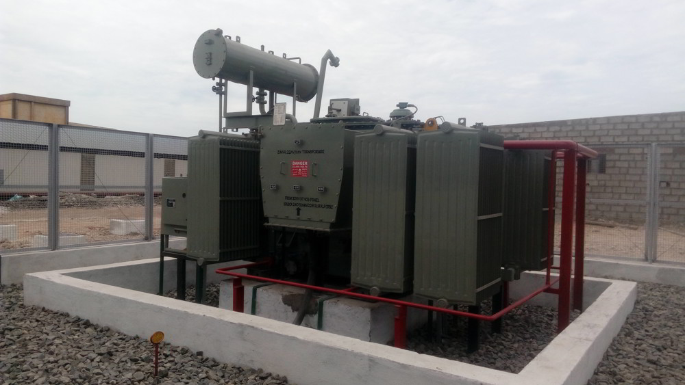
- Oil Cooled Power transformers Up to 33 KV-25MVA
- Oil Cooled HT Metering unit Up to 33 KV
- Oil Cooled Distribution transformers Up to 33 KV-3MVA
- Epoxy Resin Cast Transformers Up to 33 KV-800KVA
- Air Cooled Resin Impregnated Dry Type and Distribution Transformers Up to 33KV-3000KVA
- Oil Cooled Current and Potential Transformers Up to 33 KV
- Unitized Substation packages Up to 33 KV
Core :
The core is built from prime grade, low loss, non-ageing, CRGO steel laminations. The manufacturing of core conforms to latest standards and free from the scale degree of waviness brittleness, tolerance on thickness, permeability and inherent loss due to hysteresis & eddy current. The core is made of step- lap construction with mitred joints to reduce no- load losses. Adequate cooling ducts with directed oil flow are provided for cooling of core without affecting the flux distribution.
Top and bottom yoke clamps are secured by tie rods. Core columns are fastened using high resistant yoke bonding.
Insulation between the core and clamping structure is tested at 2500volts before the windings are assembled. The core is bonded to the clamping structure and to the tank to ensure effective earthing.
Resultant rugged structure has low loss, low magnetization current and low sound level.
Transformer Core coil Assembly :
- The core assembly is vertically placed with the foot plate touching the ground and the limps.
- Cylinder made out of insulating press board/pressphan paper is wrapped on all the three limbs.
- Low Voltage Coil is placed on the insulated core limbs
- Insulating block of specified thickness and number are placed both at the top and bottom of the L.V.Coil.
- Cylinder made out of corrugated paper or plain cylinder with oil ducts are over L.V.Coil.
- H.V.Coils are placed over the cylinder.
- Gap between each section of H.V.Coils including top & bottom clearances is maintained with the help of oil ducts, as per the design / drawings.
- The Top Yoke is refilled. Top core frame including core bolts and tie rods are fixed in position.
- Primary and secondary windings will be connected as per the requirements.
- Phase barrier between H.V.phases are placed as per requirement.
- Connections to the tapping switch or OLTC (if required) are made.
- Vilas Transcore's, TUV ISO 9001 ceritify company is being used.
Windings :
Windings are designed to meet electrical , thermal and mechanical requirements. Windings are manufactured with electrolytic copper conductors of maximum purity. Windings are cylindrical in shape. Depending on the voltage and current transformer windings can be helical, continuous or interleaved disc, spiral, cross-over coils.
Windings are wound with adequate bracing and securing tapes so as to achieve strong structure. Interlayer cooling ducts are provided to limit the temperature gradient between windings and oil. This helps in limiting the hot spot temperature and minimizes the insulation deterioration.
Transpositions are made in multiple conductor windings so as to achieve uniform current distribution and to minimize circulating currents.
Before assembly onto the core, windings are pre-shrunk to a pre-determined shrinkage force to ensure better short circuit withstand capability.
Tank :
The tank is made of welded steel sheets and reinforced structure. Structural base is designed to permit skidding or rolling in either direction. Transformers are provided with bolted removable lid and appropriate inspection access. Where required, LV outlet on tank is fitted with non-magnetic plates.
All tanks are pressure tested after their fabrication.
Tanks are cleaned and shot blasted. Internal surface is painted with hot oil resistant coating. External surface is painted as per Electrotherm (adopted from best paint practices) procedure. Exterior paint shade is to Customer's specification.
Cooling is effected by tank mounted radiators or by means of corrugations on the tank side or by separately mounted cooling units. Cooling arrangements provision will be decided based on size of the transformer and customer specifications. If required, air blast fans or forced oil circulation employing oil pumps or water-cooled heat exchangers can be provided.